Mastering the art of wiring security cameras is crucial for robust home and business protection. This guide provides a comprehensive, step-by-step approach to installing wired security camera systems, ensuring reliability and optimal performance for your surveillance needs.
Understanding Wired Security Camera Systems
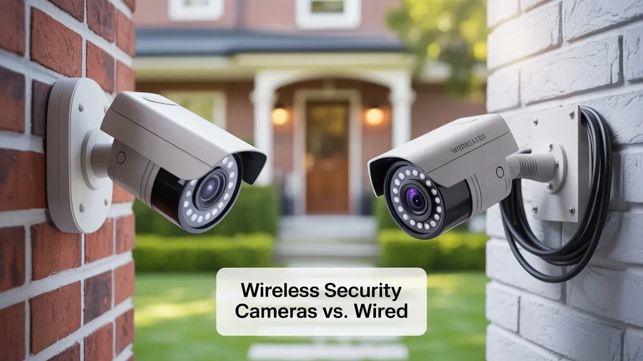
Wired security camera systems, often referred to as CCTV (Closed-Circuit Television) systems, offer a robust and reliable solution for surveillance. Unlike their wireless counterparts, wired systems transmit data and power through physical cables, which inherently provides a more stable connection, higher data transfer rates, and enhanced security against signal interference or hacking. In 2025-26, the demand for such dependable systems continues to grow, driven by increasing security concerns and the desire for continuous, high-quality monitoring. The average cost of a professional installation for a wired system can range from $500 to $2,000, depending on the number of cameras and complexity of the setup, but DIY installations can significantly reduce this cost. Understanding the fundamental components is the first step to successfully wiring your own system.
The Core Components of a Wired System
A typical wired security camera system comprises several key components that work in tandem to capture, transmit, and store video footage:
- Cameras: These are the eyes of your system, capturing visual information. Wired cameras require a physical connection for both data and power.
- Cabling: This is the backbone of the system, transmitting video signals and power. The type of cable used depends on the camera technology (e.g., coaxial for analog, Ethernet for IP).
- Power Supply: Cameras need a power source. This can be a dedicated power adapter for each camera, a centralized power box, or delivered over the Ethernet cable itself (PoE).
- Recording Device: This is where your footage is stored. The two primary types are DVRs (Digital Video Recorders) for analog cameras and NVRs (Network Video Recorders) for IP cameras.
- Monitor: Used for live viewing and playback of recorded footage.
The choice between analog and IP systems often dictates the type of wiring and recording device you'll use. IP systems, leveraging Ethernet cables, are generally considered more modern and offer higher resolution and greater flexibility, while analog systems, using coaxial cables, can be a more budget-friendly option and are sometimes easier to install in existing infrastructure.
Advantages of Wired Systems in 2025-26
Despite the rise of wireless technology, wired systems maintain a strong presence due to their inherent advantages, especially in professional and high-security applications. As of 2025-26, these benefits remain highly relevant:
- Reliability: Wired connections are far less susceptible to interference from other wireless devices, walls, or distance limitations that can plague wireless systems. This ensures a consistent and stable feed.
- Security: Physical cables are inherently more secure than wireless signals, which can be intercepted or jammed. For sensitive locations, this is a critical factor.
- Performance: Wired systems, particularly IP cameras, can support higher resolutions (4K and beyond) and frame rates, leading to clearer, more detailed footage. They also offer lower latency.
- Power over Ethernet (PoE): For IP cameras, PoE allows a single Ethernet cable to transmit both data and power, simplifying installation and reducing the need for separate power outlets near each camera.
- Longevity: Wired systems are often built with more durable components and are less prone to obsolescence due to evolving wireless standards.
The investment in a wired system is an investment in peace of mind, knowing your surveillance is consistently operational and secure.
Types of Wired Cameras and Their Wiring
The type of wired camera you choose will directly influence the type of cabling and connectors you'll need. Understanding these differences is crucial for a successful installation. The primary distinction lies between analog CCTV cameras and modern IP (Internet Protocol) cameras.
Analog CCTV Cameras and Coaxial Cabling
Analog CCTV systems have been the standard for decades. They use coaxial cables, most commonly RG59 or RG6, to transmit video signals from the camera to a DVR. These cables are designed to carry analog video signals and are relatively robust.
- RG59 Cable: This is the most common type for analog CCTV. It consists of a central conductor surrounded by an insulator, a braided metal shield, and an outer jacket. It's suitable for shorter runs (up to 500 feet) without significant signal degradation.
- RG6 Cable: Similar to RG59 but with a thicker conductor and better shielding, RG6 is designed for longer runs and higher frequencies, making it suitable for cable TV and satellite. It can also be used for CCTV, especially for longer distances or if higher quality is desired.
- Connectors: Analog cameras typically use BNC (Bayonet Neill–Concelman) connectors for video signal transmission. These provide a secure twist-on connection.
- Power: Analog cameras require a separate power cable, usually a 2.1mm DC barrel connector, which runs from a power supply unit (PSU) to the camera. This means two cables per camera: one for video and one for power.
Example Scenario: Imagine installing a basic analog camera to monitor your front porch. You would run a single RG59 coaxial cable from the camera's location to your DVR. Additionally, you would run a separate power cable from a nearby power outlet (or a centralized power distribution box) to the camera. Both cables would terminate with their respective connectors (BNC for video, DC barrel for power) and plug into the camera.
IP Cameras and Ethernet Cabling (Cat5e/Cat6)
IP cameras are the modern standard, transmitting digital video data over a network using Ethernet cables. This offers significant advantages in terms of resolution, features, and installation flexibility, especially with Power over Ethernet (PoE).
- Ethernet Cables (Cat5e/Cat6): These cables are used for data transmission in computer networks and are ideal for IP cameras. Cat5e is sufficient for most IP camera applications, supporting speeds up to 1 Gbps. Cat6 offers improved performance and is recommended for longer runs or higher bandwidth needs, supporting speeds up to 10 Gbps over shorter distances.
- Connectors: Ethernet cables use RJ45 connectors, which are standard for network devices.
- Power over Ethernet (PoE): This is a game-changer for IP camera installations. PoE technology allows a single Ethernet cable to carry both data and electrical power from a PoE-enabled switch or injector to the camera. This eliminates the need for a separate power cable and outlet near the camera, greatly simplifying wiring and allowing for more flexible camera placement. Most modern IP cameras are PoE-compatible.
- Power Adapters (Non-PoE): If you are using IP cameras that do not support PoE, or if your network switch is not PoE-enabled, you will need to provide a separate power adapter for each camera, similar to analog systems.
Example Scenario: Installing a 4K IP camera to monitor your backyard. You would run a single Cat6 Ethernet cable from the camera's location to your network switch or NVR. If the camera and switch/NVR support PoE, this single cable will provide both data connectivity and power. If not, you'll need to run a separate power cable to the camera.
Hybrid Systems and Considerations
Some systems offer hybrid capabilities, allowing for a mix of analog and IP cameras, often through specialized DVRs or encoders. However, for a dedicated wired system, it's generally best to stick to one type for simplicity and optimal performance. When choosing, consider:
- Resolution Needs: IP cameras offer significantly higher resolutions (1080p, 4MP, 8MP/4K) compared to most analog cameras (typically 720p or 1080p for HD-over-coax).
- Existing Infrastructure: If you have existing coaxial cabling, an analog system or an HD-over-coax system might be a more straightforward upgrade.
- Budget: Analog systems are often cheaper upfront, but IP systems can offer better long-term value due to higher quality and PoE convenience.
- Future-Proofing: IP systems are generally considered more future-proof due to their digital nature and compatibility with evolving network technologies.
Understanding these differences will guide your planning and ensure you select the right components for your specific needs.
Planning Your Security Camera Installation
A well-planned installation is the cornerstone of an effective and reliable security camera system. Rushing this phase can lead to suboptimal camera placement, insufficient cable lengths, power issues, and ultimately, a system that doesn't meet your security objectives. For 2025-26, meticulous planning is more critical than ever as systems become more sophisticated.
Assessing Your Security Needs
Before you even think about cables or cameras, define what you want your system to achieve. Ask yourself:
- What areas need surveillance? Identify key entry points (doors, windows), vulnerable areas (driveways, backyards, garages), and common areas of activity.
- What level of detail is required? Do you need to identify faces from a distance (requiring higher resolution cameras) or simply detect motion in a general area?
- What are the environmental conditions? Will cameras be exposed to extreme weather (requiring outdoor-rated, weatherproof cameras)? Will they be in low-light or completely dark areas (requiring cameras with good night vision)?
- What is your budget? This will influence the type of cameras, number of cameras, and whether you opt for a DIY or professional installation.
For 2025-26, consider the increasing prevalence of smart home integration. Many modern wired systems can integrate with other smart devices, so think about your future integration goals.
Determining Camera Placement
Strategic camera placement is paramount. Consider the following:
- Coverage: Ensure cameras overlap coverage where necessary, especially at entry points, to avoid blind spots.
- Height: Mount cameras high enough to prevent tampering but low enough to capture useful detail. Generally, 8-10 feet is a good starting point for exterior cameras.
- Angle: Position cameras to capture the desired field of view without significant obstructions. Avoid pointing cameras directly at bright light sources (like the sun) which can wash out the image.
- Power and Network Access: Plan for how you will get power and network connectivity to each camera location. This is where PoE becomes a significant advantage for IP systems.
- Aesthetics and Privacy: Be mindful of where cameras are pointed. Avoid infringing on neighbors' privacy.
Example: For a front door, a camera placed above the doorframe, angled slightly down, can capture faces of visitors and activity in the immediate vicinity. For a driveway, a wider-angle camera positioned at the corner of the house might be ideal. For a backyard, consider cameras covering gates and potential access points.
Mapping Cable Runs
This is where the "how to wire" aspect truly begins. You need to plan the path each cable will take from the camera to your recording device (DVR or NVR).
- Identify the Central Location: Determine where your DVR or NVR will be housed. This is typically a secure, climate-controlled location like an office, closet, or basement.
- Measure Distances: Use a measuring tape to accurately determine the length of cable required for each camera. It's always better to have a little extra cable than to be short.
- Consider Obstacles: Note any walls, ceilings, floors, conduits, or other obstructions that cables will need to pass through.
- Choose the Cable Path: Decide whether cables will run through attics, crawl spaces, conduits, or along exterior walls. For outdoor runs, ensure cables are protected from the elements and UV exposure.
- PoE Considerations: If using PoE, the cable run is simpler as it's a single Ethernet cable. Ensure your PoE switch or injector is located near your NVR or within a reasonable distance to power the cameras.
- Analog System Specifics: For analog systems, you'll need to plan two separate cable runs per camera: one coaxial for video and one power cable. This doubles the cabling effort.
Tip: Sketching a floor plan and marking the camera locations, recording device location, and planned cable routes can be incredibly helpful.
Understanding Cable Length Limitations
Cable length is a critical factor in signal quality and system performance.
- Analog (RG59): Signal degradation can occur over longer distances. For RG59, it's generally recommended to keep runs under 500 feet (approx. 150 meters) to maintain good video quality. For longer runs, consider RG6 or signal boosters.
- IP (Ethernet): Standard Ethernet (Cat5e/Cat6) has a maximum reliable transmission distance of 328 feet (100 meters) for data. This limit applies whether you're using PoE or just data transmission. For longer distances, you'll need network switches to extend the range or use fiber optic converters.
Ensure your planned cable runs adhere to these limitations to avoid performance issues.
Gathering Your Tools and Materials
Having the right tools and materials readily available before you begin wiring will make the process smoother, safer, and more efficient. This is essential for a successful DIY installation, saving you time and potential frustration.
Essential Tools for Wiring Security Cameras
Depending on the type of system (analog vs. IP) and installation environment, you'll need a selection of tools. For 2025-26, many DIYers are opting for IP systems, so Ethernet-related tools are increasingly common.
- Wire Strippers/Cutters: Essential for preparing coaxial and Ethernet cables, stripping insulation, and cutting them to length.
- Crimping Tool: Specifically, an RJ45 crimping tool for Ethernet cables and a BNC crimping tool for coaxial cables.
- Punch Down Tool: Useful for terminating Ethernet cables into patch panels or keystone jacks.
- Screwdrivers: A set of Phillips and flathead screwdrivers for mounting cameras, enclosures, and other hardware.
- Drill and Drill Bits: For creating holes in walls, ceilings, or mounting surfaces to pass cables or mount cameras.
- Fish Tape or Pulling Rods: Invaluable for pulling cables through walls, ceilings, and conduits, especially in tight spaces.
- Ladder: For reaching higher mounting locations. Ensure it's stable and used safely.
- Stud Finder: To locate wall studs for secure mounting points.
- Voltage Tester (Non-Contact): Crucial for electrical safety when working near power sources.
- Cable Tester: Highly recommended for Ethernet cables to verify proper wiring and continuity before connecting devices.
- Safety Glasses: Always wear eye protection when drilling, cutting, or working overhead.
- Work Gloves: To protect your hands.
- Zip Ties and Cable Management: For organizing and securing cables neatly.
Necessary Materials
The specific materials will depend on whether you're installing an analog or IP system. Always purchase slightly more than you think you'll need.
- Cameras: The security cameras themselves. Ensure they are appropriate for the environment (indoor/outdoor, night vision capabilities).
- Cabling:
- For Analog: RG59 or RG6 coaxial cable (bulk spools are economical).
- For IP: Cat5e or Cat6 Ethernet cable (bulk spools). Ensure it's suitable for your intended environment (e.g., plenum-rated for in-wall runs in some commercial settings, outdoor-rated for exterior runs).
- Connectors:
- For Analog: BNC connectors (crimp-on or compression type). DC barrel connectors (male and female) for power.
- For IP: RJ45 connectors for Ethernet cables.
- Power Supply:
- For Analog: A multi-camera power distribution box or individual power adapters for each camera.
- For IP (Non-PoE): Individual power adapters for each camera.
- For IP (PoE): A PoE-enabled network switch or PoE injectors.
- Recording Device: DVR for analog, NVR for IP.
- Monitor: For live viewing and playback.
- Network Switch (if NVR doesn't have enough ports): For connecting multiple IP cameras.
- Mounting Hardware: Screws, anchors, mounting brackets, junction boxes (especially for outdoor installations to protect connections).
- Conduit (optional but recommended for outdoor/exposed runs): To protect cables from damage and weather.
- Weatherproof Enclosures (optional): For protecting cameras and connections in harsh environments.
Pre-Installation Checks
Before you start running cables, it's wise to perform a few checks:
- Test Cables: If using Ethernet, use a cable tester to ensure each cable run is correctly wired and has continuity. This saves immense troubleshooting time later.
- Test Connectors: Ensure BNC and RJ45 connectors are properly crimped or attached. A loose connection is a common cause of failure.
- Test Power Supply: Verify your power supply units or PoE switch are functioning correctly.
Having all your tools and materials organized and ready will significantly streamline the wiring process.
Step-by-Step Guide: How to Wire Security Cameras
This section provides a practical, step-by-step guide to wiring your security cameras. We'll cover both analog and IP systems, highlighting the key differences in the process.
Step 1: Prepare Your Workspace and Tools
Ensure you have all your tools and materials laid out and accessible. Familiarize yourself with the connectors and cables you'll be using. If you're working with Ethernet cables, consider pre-making some cables to your common lengths if you have a consistent setup.
Step 2: Run the Cables
This is the most labor-intensive part. Based on your planning, begin running the cables from each camera location to your central recording device location (DVR or NVR).
- Drill Holes: Carefully drill holes through walls, ceilings, or other obstructions. Ensure you are not drilling into existing electrical wires or plumbing. Use a stud finder and be cautious.
- Pull Cables: Use fish tape or pulling rods to guide the cables through walls and ceilings. If running cables outdoors, use conduit for protection against weather and physical damage.
- Label Cables: As you run each cable, label both ends with the camera location (e.g., "Front Door," "Backyard Gate") and the type of cable (e.g., "Video," "Power," "Ethernet"). This is crucial for organization.
- Avoid Interference: Try to keep video cables (especially coaxial) away from electrical power cables to minimize interference. If they must cross, do so at a 90-degree angle.
- Adhere to Length Limits: Double-check that your cable runs do not exceed the recommended maximum lengths for your cable type (328 ft for Ethernet, 500 ft for RG59).
Step 3: Terminate the Cables
Once the cables are run, you need to attach the appropriate connectors to each end.
For Analog Systems (Coaxial Cables):
- Prepare the Coaxial Cable: Using wire strippers, carefully strip about 1/2 inch of the outer jacket. Then, strip about 1/4 inch of the inner insulation, exposing the center conductor. Be careful not to nick the center conductor. Fold back the braided shield.
- Attach the BNC Connector: Slide the BNC connector onto the cable. The center conductor should protrude through the center pin of the connector. The braided shield should be tucked behind the connector's ferrule.
- Crimp the Connector: Using a BNC crimping tool, crimp the connector firmly onto the cable. Ensure the crimp is secure. For compression connectors, follow the manufacturer's instructions, which usually involve a special compression tool.
- Prepare the Power Cable: Strip a small amount of insulation from the positive (+) and negative (-) wires of the power cable.
- Attach DC Barrel Connector: Solder or use screw-terminal DC barrel connectors to the power wires, matching polarity (positive to positive, negative to negative).
For IP Systems (Ethernet Cables):
- Prepare the Ethernet Cable: Strip about 1 inch of the outer jacket from the Ethernet cable. Untwist the pairs of wires.
- Arrange Wires: Arrange the eight wires according to the T568B standard (or T568A, but be consistent). The standard order is: Orange/White, Orange, Green/White, Blue, Blue/White, Green, Brown/White, Brown.
- Trim Wires: Trim the ends of the wires so they are all even and about 1/2 inch long.
- Insert into RJ45 Connector: Carefully insert the arranged wires into the RJ45 connector, ensuring each wire is seated fully in its channel and the outer jacket extends slightly into the connector for strain relief.
- Crimp the Connector: Using an RJ45 crimping tool, crimp the connector firmly onto the cable. Ensure the tool engages the connector's locking tab.
Important: If you are using pre-made Ethernet patch cables, you can skip this termination step for the ends that connect to your switch or NVR.
Step 4: Mount the Cameras
With cables run and terminated, it's time to mount the cameras.
- Positioning: Mount cameras in their planned locations, ensuring they are secure and at the desired angle.
- Weatherproofing: For outdoor cameras, ensure all connections are made within weatherproof junction boxes or use weatherproof connectors and enclosures.
- Connect Cables: Connect the terminated cables to the camera's input ports. For analog, this means connecting the BNC connector for video and the DC barrel connector for power. For IP, it's plugging in the RJ45 Ethernet cable.
Step 5: Connect to the Recording Device
Now, connect the other ends of your cables to your DVR or NVR.
- Analog DVR: Connect the BNC video cables from each camera to the corresponding video input ports on the DVR. Connect the DC power cables to the power distribution box, which will then be plugged into a wall outlet.
- IP NVR: Connect the RJ45 Ethernet cables from each camera to the LAN port on the NVR (if it has built-in PoE ports) or to a separate PoE switch. If using a separate switch, connect the NVR to the switch via an Ethernet cable.
This step-by-step process, when followed diligently, will result in a properly wired security camera system.
Powering Your Wired Security Cameras
Powering your security cameras is a critical aspect of their operation. The method of power delivery varies significantly between analog and IP systems, and even within IP systems themselves. Understanding these options ensures your cameras are always operational.
Powering Analog Cameras
Analog cameras require a separate power source, typically 12V DC or 24V AC. The most common setup involves:
- Individual Power Adapters: Each camera is connected to a dedicated power adapter plugged into a nearby wall outlet. This is simple but can lead to a tangle of wires and requires an outlet at each camera location, which is often impractical.
- Multi-Camera Power Distribution Box: This is a more organized solution. A single, higher-amperage power supply unit (PSU) is housed in a central location (e.g., near the DVR). This PSU then connects to a power distribution box that splits the power into multiple smaller outputs, each running a separate power cable to an individual camera. This consolidates the power source and reduces the number of wall outlets needed.
Key Considerations for Analog Power:
- Voltage and Amperage: Ensure the power supply voltage (12V DC or 24V AC) and total amperage output match the requirements of all connected cameras. Overloading a power supply can cause it to fail or lead to unstable camera operation.
- Cable Gauge: For longer power runs, using a thicker gauge wire (lower AWG number) can help prevent voltage drop, ensuring the camera receives adequate power.
- Polarity: For DC power, correct polarity is essential. Reversing polarity can damage the camera.
Powering IP Cameras: The Power over Ethernet (PoE) Revolution
Power over Ethernet (PoE) has revolutionized IP camera installations. It allows a single Ethernet cable to carry both data and electrical power, significantly simplifying wiring and installation.
- PoE Standards: There are several PoE standards (e.g., IEEE 802.3af, 802.3at/PoE+, 802.3bt/PoE++). Cameras and power sourcing equipment (PSE) must be compatible. Most modern IP cameras use PoE or PoE+.
- PoE Switches: These are network switches that have built-in PoE capabilities on some or all of their ports. You connect your IP cameras to the PoE ports on the switch, and the switch provides both data connectivity and power. The switch itself is then plugged into your network and power.
- PoE Injectors: A PoE injector acts like a mid-span device. It takes a standard Ethernet connection from your network and injects power into the cable, which then connects to the IP camera. This is useful if you have a non-PoE switch but need to power a few cameras.
- NVR with Built-in PoE: Many NVRs designed for IP camera systems come with integrated PoE ports. This consolidates your recording device and PoE switch into one unit, further simplifying installation.
Benefits of PoE:
- Simplified Wiring: One cable instead of two.
- Reduced Installation Costs: No need for electricians to install power outlets near cameras.
- Flexible Placement: Cameras can be installed in locations without readily available power outlets.
- Remote Management: Some PoE systems allow for remote power cycling of cameras.
Powering IP Cameras Without PoE
If your IP cameras do not support PoE, or if your network infrastructure is not PoE-enabled, you will need to provide power separately:
- Individual Power Adapters: Similar to analog cameras, each IP camera will require its own power adapter plugged into a nearby outlet.
- Centralized Power Box: You can use a multi-output 12V DC power supply and distribution box, similar to analog systems, but ensuring the voltage and amperage are suitable for your IP cameras.
When choosing your power solution, always consult the camera manufacturer's specifications for voltage, amperage, and power consumption requirements. For 2025-26, PoE remains the preferred and most efficient method for powering IP cameras.
Connecting to Your NVR or DVR
The Network Video Recorder (NVR) for IP systems and the Digital Video Recorder (DVR) for analog systems are the central hubs of your surveillance setup. Properly connecting your cameras to these devices ensures data is received, processed, and stored.
Connecting Analog Cameras to a DVR
The process is straightforward due to the direct, dedicated connections.
- Video Connections: Connect the BNC connector from each camera's coaxial cable to a corresponding numbered video input port on the back of the DVR. For example, the cable from your front door camera connects to "CH1" (Channel 1), the backyard camera to "CH2," and so on.
- Power Connections: Ensure the power cables from each camera are connected to your power distribution system, which is then plugged into a mains power outlet. The DVR itself will also need to be powered via its own power adapter.
- Network Connection (for Remote Access): Most DVRs have an Ethernet port (LAN) for connecting to your home or office network. This allows you to access the DVR remotely via a smartphone app or web browser. Connect an Ethernet cable from this port to your router or network switch.
- Monitor Connection: Connect a monitor to the DVR's video output (HDMI or VGA) so you can view live feeds and playback recordings.
Connecting IP Cameras to an NVR
Connecting IP cameras to an NVR can be done in a few ways, depending on whether the NVR has built-in PoE ports.
Method 1: NVR with Built-in PoE Ports
This is the simplest and most common setup for IP systems.
- Connect Cameras to NVR: Run the Ethernet cable from each IP camera directly to one of the NVR's PoE Ethernet ports. The NVR will automatically detect the camera, provide it with power, and establish a network connection.
- NVR Network Connection: The NVR will have a separate LAN port for connecting to your router or network switch. This allows the NVR to access the internet for remote viewing and software updates. Connect an Ethernet cable from this LAN port to your router.
- Monitor Connection: Connect a monitor to the NVR's HDMI or VGA output for local viewing and configuration.
Method 2: Using a Separate PoE Switch
This method is used when the NVR has fewer PoE ports than cameras, or if you prefer to manage your network devices separately.
- Connect Cameras to PoE Switch: Run the Ethernet cable from each IP camera to a port on your PoE switch. The switch will power the cameras and provide network connectivity.
- Connect PoE Switch to NVR: Connect an Ethernet cable from one of the ports on the PoE switch to one of the NVR's Ethernet ports (these ports on the NVR may not be PoE-enabled in this scenario, but are for data).
- Connect NVR to Router: Connect another Ethernet cable from the NVR's LAN port to your router or network switch. This allows the NVR to access the internet.
- Monitor Connection: Connect a monitor to the NVR's HDMI or VGA output.
Method 3: Using a Non-PoE Switch (or NVR without PoE)
If you're using IP cameras without PoE and a non-PoE switch or NVR, you'll need separate power for each camera.
- Connect Cameras to Power: Power each IP camera using its individual power adapter or a centralized power distribution box.
- Connect Cameras to Switch: Run an Ethernet cable from each camera's network port to a port on your network switch.
- Connect Switch to NVR: Connect an Ethernet cable from a port on the switch to the NVR's LAN port.
- Connect NVR to Router: Connect the NVR's LAN port to your router.
- Monitor Connection: Connect a monitor to the NVR's HDMI or VGA output.
Initial Setup and Configuration
Once everything is physically connected, you'll need to power on your DVR/NVR and cameras. The initial setup will involve:
- Formatting Storage: If your DVR/NVR has a hard drive, you'll likely need to format it.
- Camera Detection/Pairing: For IP systems, the NVR will scan the network and detect connected cameras. You may need to manually add cameras or enter their IP addresses and passwords.
- Network Configuration: Set up your DVR/NVR's network settings (IP address, subnet mask, gateway, DNS) to ensure it can communicate with your router and the internet for remote access.
- Date and Time: Set the correct date and time for accurate recording logs.
Refer to your DVR/NVR's user manual for specific setup instructions, as interfaces and procedures can vary between manufacturers.
Testing and Troubleshooting Your System
After installation and initial setup, thorough testing is essential to ensure your security camera system is functioning correctly. Even the best installations can encounter issues, so knowing how to troubleshoot is key.
Comprehensive Testing Procedures
Systematically test each component and function:
- Live View: Access the live view on your monitor or mobile app. Check that all cameras are displaying a clear image. Verify the image quality, color accuracy, and frame rate.
- Night Vision: Test the cameras in low-light conditions or at night. Ensure the infrared (IR) illuminators are working and providing adequate visibility. Check for any glare or reflections that might be interfering.
- Motion Detection: Configure motion detection settings for each camera and test them by walking through the monitored areas. Ensure alerts are triggered correctly and that the system records when motion is detected.
- Recording Playback: Review recorded footage. Check for any dropped frames, corrupted video, or gaps in recordings. Ensure the timestamps are accurate.
- Audio (if applicable): If your cameras have audio capabilities, test the microphone and speaker functions.
- Remote Access: Test remote viewing from your smartphone or computer. Ensure you can connect reliably and view live feeds and recordings.
- Network Connectivity: Verify that your NVR/DVR is properly connected to your network and the internet.
- Power Stability: Monitor cameras for any signs of power interruption or flickering images.
Common Troubleshooting Scenarios and Solutions
Here are some common issues and how to address them:
| Problem | Possible Cause | Solution |
|---|---|---|
| No Video Signal / Camera Offline | Loose cable connection | Check all BNC or RJ45 connections at the camera and DVR/NVR. Reseat or re-crimp if necessary. |
| Faulty cable | Test the cable with a cable tester. Replace if damaged. | |
| Camera not powered | For analog, check the power adapter and connections. For IP/PoE, ensure the switch/injector is powered and providing power. Check camera's power indicator light if available. | |
| Incorrect DVR/NVR channel configuration | Ensure the camera is assigned to the correct input channel on the DVR/NVR. For IP, ensure the camera is properly added to the NVR. | |
| Poor Image Quality (Grainy, Blurry, Distorted) | Low-quality cabling or connectors | Use high-quality RG59/RG6 or Cat5e/Cat6 cables and properly terminated connectors. |
| Signal interference | Keep video cables away from power cables. Ensure proper shielding on coaxial cables. | |
| Dirty camera lens | Clean the camera lens with a soft, lint-free cloth. | |
| Camera not focused correctly | Adjust the camera's focus if it's a varifocal lens. | |
| Night Vision Not Working / Poor IR Performance | IR LEDs obstructed or damaged | Ensure nothing is blocking the IR LEDs on the camera. Check for physical damage. |
| Insufficient power | Ensure the camera is receiving adequate power. Low voltage can affect IR performance. | |
| Camera is in a location with ambient light | Some cameras may not activate IR if ambient light is sufficient. Check camera settings. | |
| Motion Detection Not Triggering / False Alarms | Incorrect sensitivity settings | Adjust the motion detection sensitivity and zone settings in the DVR/NVR. |
| Environmental factors (wind, shadows, insects) | Refine motion detection zones to exclude areas prone to false triggers. Consider AI-based detection if available. | |
| Camera angle issues | Ensure the camera angle is optimal and not prone to triggering by irrelevant movement. | |
| Remote Access Not Working | Incorrect network configuration | Double-check IP address, subnet mask, gateway, and DNS settings on the DVR/NVR and router. Ensure port forwarding is correctly configured if necessary. |
| Firewall blocking connection | Ensure your router's firewall is not blocking the necessary ports. | |
| Internet connectivity issues | Verify your internet connection is stable. | |
| Incorrect mobile app or DDNS setup | Follow the manufacturer's instructions precisely for remote access setup. |
When to Call a Professional
While many issues can be resolved with basic troubleshooting, there are times when professional assistance is recommended:
- Complex electrical work is required.
- You're uncomfortable working with power or drilling into walls.
- The troubleshooting steps are beyond your technical expertise.
- The system is consistently failing despite your efforts.
A qualified technician can diagnose and resolve persistent problems efficiently.
Advanced Considerations and Best Practices
Beyond the basic wiring and setup, several advanced considerations and best practices can significantly enhance the performance, security, and longevity of your wired security camera system. Implementing these in 2025-26 will ensure you're leveraging the full potential of your surveillance investment.
Cable Management and Protection
Neatly organized and protected cables are crucial for system reliability and aesthetics.
- Conduit: For exterior runs or areas exposed to potential damage, running cables through UV-resistant PVC conduit is highly recommended. This protects against weather, physical impact, and tampering.
- Junction Boxes: Use weatherproof junction boxes at camera locations, especially for outdoor installations. These provide a protected enclosure for cable splices and connectors, safeguarding them from moisture and dust.
- Cable Ties and Clips: Use zip ties, Velcro straps, or cable clips to neatly bundle and secure cables along walls, ceilings, or within conduits. This prevents sagging, tripping hazards, and makes maintenance easier.
- Avoid Sharp Bends: Do not bend cables (especially Ethernet) tighter than their minimum bend radius, as this can damage internal wires and affect signal integrity.
Network Security for IP Systems
As IP cameras are network devices, their security is paramount.
- Strong Passwords: Change default passwords on all cameras and the NVR immediately. Use strong, unique passwords that combine uppercase and lowercase letters, numbers, and symbols.
- Firmware Updates: Regularly update the firmware on your cameras and NVR. Manufacturers release updates to patch security vulnerabilities and improve performance.
- Network Segmentation: For enhanced security, consider placing your IP cameras on a separate VLAN (Virtual Local Area Network) from your main network. This isolates them and limits potential access to other devices on your network.
- Firewall Configuration: Ensure your router's firewall is properly configured to block unauthorized access. Only open ports necessary for remote access and ensure they are secured.
- Disable Unused Services: If your cameras or NVR have features you don't use (e.g., UPnP, Telnet), disable them to reduce the attack surface.
Power Over Ethernet (PoE) Best Practices
While PoE simplifies wiring, some best practices ensure optimal performance:
- PoE Budget: Be aware of the total power output (budget) of your PoE switch or injector. Ensure it can supply enough power to all connected cameras simultaneously. Exceeding the budget can lead to unstable power or device failure.
- Cable Quality: Use good quality Cat5e or Cat6 Ethernet cables. Poor quality cables can lead to voltage drop, affecting camera performance and reliability.
- Distance Limitations: Remember the 328-foot (100-meter) limit for Ethernet. For longer runs, use PoE extenders or network switches to regenerate the signal and power.
Environmental Considerations
The environment where cameras are installed impacts their lifespan and performance.
- Temperature Extremes: Ensure cameras are rated for the ambient temperature range. Extreme heat or cold can damage internal components.
- Moisture and Dust: Use IP-rated weatherproof cameras and enclosures for outdoor or high-moisture environments.
- Vandal Resistance: In public or high-risk areas, consider vandal-proof camera housings to prevent tampering or damage.
System Scalability and Future-Proofing
Plan for future expansion.
- NVR/DVR Capacity: Choose an NVR/DVR with more channels than you currently need to allow for additional cameras later. Consider the hard drive capacity required for your desired recording retention period, and opt for a system that supports larger drives or RAID configurations for redundancy.
- Resolution Standards: Invest in cameras with higher resolutions (4K is becoming standard for critical areas in 2025-26) to ensure clarity and detail for years to come.
- Network Infrastructure: If using IP cameras, ensure your network infrastructure (router, switches) can support the required bandwidth, especially for multiple high-resolution streams.
By incorporating these advanced considerations and best practices, you can build a robust, secure, and future-proof wired security camera system that provides reliable surveillance for years to come.
Conclusion
Successfully wiring security cameras involves meticulous planning, the right tools, and a systematic approach to installation. Whether you're working with traditional analog systems and coaxial cables or modern IP cameras leveraging Ethernet and PoE, understanding the core principles of power delivery, signal transmission, and connection points is paramount. By carefully assessing your security needs, mapping out camera placements and cable runs, and adhering to best practices for cable management and network security, you can create a dependable surveillance system that offers peace of mind.
Remember that reliable power, secure connections, and adherence to cable length limitations are the bedrock of a functional wired system. For IP systems, embracing Power over Ethernet (PoE) significantly simplifies installation and offers greater flexibility. Always test your system thoroughly after installation and be prepared to troubleshoot common issues by referring to your device manuals and the guidance provided in this comprehensive guide. Investing the time in proper wiring and setup will ensure your security cameras perform optimally, providing clear, consistent footage when you need it most.